- Bộ lập trình PLC, cáp lập trình
- Màn hình HMI
- Cảm biến, phụ kiện
- Biến tần, khởi động mềm
- Máy cắt, Aptomat, khởi động từ
- Thiết bị đo lường, bảo vệ
- Thiết bị công nghiệp, tự động hóa
- Thủy lực, khí nén, van công nghiệp
- Motor, Servo motor, Servo Amplifier
- Thyristor, Module, SCR, SSR, Diode
- Phụ kiện tủ điện và vỏ tủ điện
- Cáp điện, ống bảo vệ cáp
- Thiết bị điện trung thế, truyền tải
- Thiết bị chống sét, kim thu sét
- Dụng cụ cầm tay, dụng cụ tool
- ATS, UPS, tụ bù, cuộn kháng
-
Thiết bị ngành xi măng, thép, nhiệt điện
-
Thiết bị vật tư điện nhẹ-viễn thông
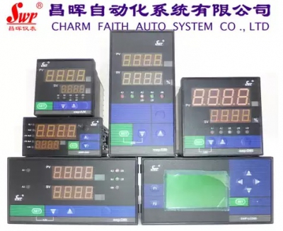
Đồng hồ đo hiển thị số Changhui Instrument SWP-ND805 905 405 705 105 PID Self-tuning Intelligent Temperature Controller
SWP-ND805-010-23-HL
SWP-ND805-020-23-HL
SWP-ND905-010-23-HL
SWP-ND905-020-23-HL
SWP-ND705-010-23-HL
SWP-ND705-020-23-HL
SWP-NS805-010-23-HL
SWP-NS805-020-23-HL
SWP-ND405-010-23-HL
SWP-ND405-020-23-HL
SWP-NS405-010-23-HL
SWP-NS405-020-23-HL
SWP-ND105-010-23-H
SWP-ND105-020-23-H
SWP-ND805-020-23-HL-P
SWP-ND905-020-23-HL-P
SWP-ND705-020-23-HL-P
SWP-NS805-020-23-HL-P
SWP-ND405-020-23-HL-P
SWP-NS405-020-23-HL-P
Tình trạng sản phẩm:
Graphic details
SWP-LED series PID self-tuning controller/PID light column display controller is suitable for systems that require high-precision measurement and control, and can automatically calculate the best PID control parameters according to the controlled object. The instrument integrates digital instruments and analog instruments, and can perform digital display control (high-brightness LED digital display) and relative analog display (light column display) of measurement signals such as temperature, pressure, liquid level, speed, etc., making the display of measured values clearer and more intuitive, and dual light column display can be selected.★SWP-LED series PID parameter self-tuning controller type spectrum
| model | Code | illustrate | ||||||||||
| SWP-N | □ | □ | □□ | -□ | □ | □ | -□□ | -□ | □ | -□ | -□ | New generation of PID self-tuning controller |
| Appearance characteristics | D S | Horizontal display Vertical display | ||||||||||
| Dimensions | 1 4 7 8 9 | 48×48mm 96×48mm (horizontal), 48×96mm (vertical) 72×72mm 160×80mm (horizontal), 80×160mm (vertical) 96×96mm | ||||||||||
| Control effect | 05 | PID self-tuning control | ||||||||||
| Communication | 0 2 4 8 9 | No communication Communication interface is RS-232C Communication interface is RS-422 Communication interface is RS-485 Communication interface special specifications | ||||||||||
| Control output mode | □ | See "Control Output Mode" | ||||||||||
| Transmission output mode | □ | See "Transmission Output Mode | ||||||||||
| Input Type | □□ | See Input Type | ||||||||||
| First alarm mode | N H L | No alarm (can be omitted) Upper limit control Lower limit control | ||||||||||
| Second alarm mode | □ | Participate in the "Alarm Method" | ||||||||||
| Feed output | P | DC24V power supply output | ||||||||||
| Power supply | W T | DC24V power supply AC85-260V power supply (switching power supply) AC220V power supply (linear power supply, can be omitted) | ||||||||||
| model | Code | illustrate | ||||||||||
| SWP-N | T□ | □□ | -□ | □ | □ | -□□ | -□ | □ | -□ | -□ | -□ | New generation of light column PID display controller |
| Dimensions | 8 | 160×80mm (horizontal), 80×160mm (vertical) | ||||||||||
| Control effect | 05 | PID self-tuning control | ||||||||||
| Communication | 0 2 4 8 9 | No communication Communication interface is RS-232C Communication interface is RS-422 Communication interface is RS-485 Communication interface special specifications | ||||||||||
| Control output mode | □ | See "Control Output Mode" | ||||||||||
| Transmission output mode | □ | See "Transmission Output Mode | ||||||||||
| Input Type | □□ | See Input Type | ||||||||||
| First alarm mode | N H L | No alarm (can be omitted) Upper limit control Lower limit control | ||||||||||
| Second alarm mode | □ | Participate in the "Alarm Method" | ||||||||||
| Feed output | P | DC24V power supply output | ||||||||||
| Power supply | W T | DC24V power supply AC85-260V power supply (switching power supply) AC220V power supply (linear power supply, can be omitted) | ||||||||||
| Appearance characteristics | X | Horizontal display Vertical display | ||||||||||
★Communication method:
| Code | 0 | 2 | 3 | 4 | 8 | 9 |
| Communication | No communication | RS-232 | Print port | RS-422 | RS-485 | Special specifications |
If the user wishes to order a special communication protocol, please indicate this when ordering.
Some instruments with printing ports cannot meet the printing function. When ordering, please choose an instrument that can meet the requirements instead.
★Control output mode:
| Selection code | 0 | 1 | 2 | 3 | 4 | 5 | 6 | 7 | 8 | 9 |
| Output method | No output | Relay | 4~20mA | 0~10mA | 1~5V | 0~5V | SCR Output | SSR Output | Special specifications | SOT output |
★Transmission output mode:
| Selection code | 0 | 2 | 3 | 4 | 5 | 8 |
| Output method | No output | 4~20mA | 0~10mA | 1~5V | 0~5V | Special specifications |
★ Input type:
| Code | Input Type | Measuring range | Code | Input Type | Measuring range | Code | Input Type | Measuring range |
| 01 | B | 400~1800℃ | 09 | Pt100.1 | -199.9~320.0℃ | 17 | 30~350Ω | -1999~9999 d |
| 02 | S | 0~1600℃ | 10 | Cu50 | -50.0~150.0℃ | 18 | Special specifications | User pending |
| 03 | K | 0~1300℃ | 11 | Cu100 | -50.0~150.0℃ | 19 | 4~20mA square root | -1999~9999 d |
| 04 | E | 0~1000℃ | 12 | 4~20mA | -1999~9999 d | 20 | 0~10mA square root | -1999~9999 d |
| 05 | T | -199.9~320.0℃ | 13 | 0~10mA | -1999~9999 d | twenty one | 1~5V square root | -1999~9999 d |
| 06 | J | 0~1200℃ | 14 | 1~5V | -1999~9999 d | twenty two | 0~5V square root | -1999~9999 d |
| 07 | WRe3~25 | 0~2300℃ | 15 | 0~5V | -1999~9999 d | twenty three | Switchable input | |
| 08 | Pt100 | -200~650℃ | 16 | 0~20mA | -1999~9999 d |
★Alarm method:
| Code | N | H | L | G | A | D |
| Alarm method | No alarm (can be omitted) | Upper limit alarm | Lower limit alarm | Deviation alarm | Out of deviation alarm | LBA Alarm |
-

- Đồng hồ đo hiển thị số Changhui Instrument High Precision Digital Display Temperature Pressure Level Controller SWP-GFC10 40 70 80 90 Liên hệ
-

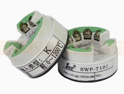
- Chuyển đổi tín hiệu nhiệt độ Changhui Instrument SWP-T101TR TC Junction Box Mounted Round Intelligent Programmable Temperature Transmitter Module Liên hệ
-

- Đồng hồ đo hiển thị số Changhui Instrument SWP-TC-C401 801 901 403 803 903-00-01-D-HL Intelligent Counter Liên hệ
-

- Đồng hồ đo hiển thị số Changhui Instrument SWP-RP-C801 403 903-00 01 02-24-HL-P Intelligent Frequency Meter Tachometer Liên hệ
-

- Đồng hồ đo hiển thị số Changhui Instrument SWP-S40 401 403 404-01/02-23-HL-PT Intelligent Single Loop Controller Liên hệ
-

- Đồng hồ đo hiển thị số Changhui Instrument SWP-C70 701 703 704-01/02-23-HHL-P Intelligent Single Channel Digital Display Controller Liên hệ
-

- Đồng hồ đo hiển thị số Changhui Instrument SWP-LK80 801 802 803 804 805 Intelligent Flow Totalizer Quantitative Controller Liên hệ
-

- Đồng hồ đo hiển thị số Changhui Instrument SWP-ND915 815 715 415PID self-tuning external given controller valve position controller Liên hệ
-

- Đồng hồ đo hiển thị số Changhui Instrument SWP-LCD-R8101 8103 8201 8203 8301 small monochrome paperless recorder Liên hệ
-

- Đồng hồ đo hiển thị số Changhui Instrument Dual Circuit SWP-D823 423 723 923 Digital Display Temperature Controller Temperature and Humidity Controller Liên hệ
-

- Đồng hồ đo hiển thị số Changhui Instrument SWP-LCD-NL80 801 802 803 LCD large screen flow totalizer quantitative controller Liên hệ
-

- Đồng hồ đo hiển thị số Changhui Instrument SWP-LCD-MD/MS80 806 807 808 LCD display multi-channel inspection control instrument Liên hệ
TÂN THÀNH CAM KẾT
- Sản phẩm, hàng hóa chính hãng.
- Giá cả cạnh tranh.
- Dịch vụ chăm sóc khách hàng tận tâm.
Thông Tin Công Ty
Chính sách và quy định
Hỗ trợ khách hàng
THÔNG TIN LIÊN HỆ:
-------------------------------
CÔNG TY TNHH THIẾT BỊ CÔNG NGHIỆP TTH
Trụ sở: số 124 ngõ 79 Yên Hoà-Cầu giấy-HN
Kinh doanh 1 : 0816.861.515
Kinh doanh 2 : 0836.861.515
Email: tthkinhdoanh@gmail.com
Email: tthkinhdoanh01@gmail.com


