- Bộ lập trình PLC, cáp lập trình
- Màn hình HMI
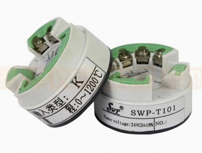
- Cảm biến, phụ kiện
- Biến tần, khởi động mềm
- Máy cắt, Aptomat, khởi động từ
- Thiết bị đo lường, bảo vệ
- Thiết bị công nghiệp, tự động hóa
- Thủy lực, khí nén, van công nghiệp
- Motor, Servo motor, Servo Amplifier
- Thyristor, Module, SCR, SSR, Diode
- Phụ kiện tủ điện và vỏ tủ điện
- Cáp điện, ống bảo vệ cáp
- Thiết bị điện trung thế, truyền tải
- Thiết bị chống sét, kim thu sét
- Dụng cụ cầm tay, dụng cụ tool
- ATS, UPS, tụ bù, cuộn kháng
-
Thiết bị ngành xi măng, thép, nhiệt điện
-
Thiết bị vật tư điện nhẹ-viễn thông
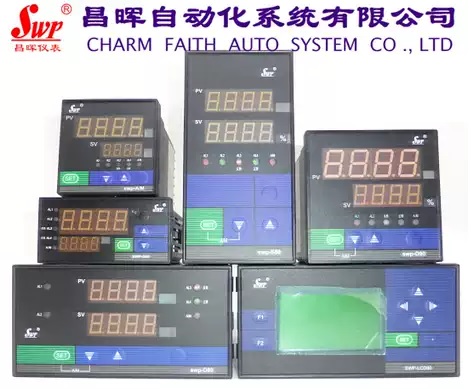
Đồng hồ đo hiển thị số Changhui Instrument SWP-LK80 801 802 803 804 805 Intelligent Flow Totalizer Quantitative Controller
SWP-LK801-01-A-HL-P
SWP-LK801-02-A-HL-P
SWP-LK802-01-AAG-HL-2P
SWP-LK802-02-AAG-HL-2P
SWP-LK803-01-AAG-HL-2P
SWP-LK803-02-AAG-HL-2P
SWP-LK804-01-AAG-HL-2P
SWP-LK804-02-AAG-HL-2P
SWP-LK805-01-AAG-HL-2P
SWP-LK805-02-AAG-HL-2P
Add 232 or 485 communication output
Tình trạng sản phẩm:
Graphic details
SWP-LK series flow totalizer controller is suitable for flow totalizer measurement and control of various liquids, steam, natural gas, general gas, etc.
| model | Code | illustrate | |||||||||||
| SWP-LK | □ | □□ | -□ | □ | -□ | □ | □ | -□ | □ | -□ | -□ | -□ | 5 -digit + 8-digit flow totalizer controller |
| Dimensions | 8 9 | 160×80mm,80×160mm 96×96mm | |||||||||||
| Control effect | 01 02 03 04 05 | Uncompensated input With compensated input Superheated steam temperature and pressure compensation - table lookup method Saturated steam with temperature and pressure compensation - table lookup method User-specific curve compensation input - look-up table method | |||||||||||
| Communication | □ | See "Communication Methods" | |||||||||||
| Output method | □ | See "Output Mode" | |||||||||||
| Flow signal type | □ | See Input Type | |||||||||||
| Pressure compensation type | □ | See Input Type | |||||||||||
| Temperature compensation type | □ | See Input Type | |||||||||||
| First alarm mode | N H L B C D | No control (or alarm, can be omitted) Upper limit control (or alarm) Lower limit control (or alarm) Flow rate control - automatic start Flow quantitative process control - automatic start Flow rate quantitative to control - automatic zeroing | |||||||||||
| Second alarm mode | N H L B C | No control (or alarm, can be omitted) Upper limit control (or alarm) Lower limit control (or alarm) Flow rate control - automatic start Flow quantitative process control-manual start | |||||||||||
| Feed output | N P 2P | No feed output (can be omitted) Single-channel DC24V feed output Dual-channel DC24V power supply output | |||||||||||
| Power supply | W T | DC24V power supply AC85-260V power supply (switching power supply) AC220V power supply (linear power supply, can be omitted) | |||||||||||
| Appearance characteristics | S | Vertical display instrument Horizontal display instrument (optional) | |||||||||||
★Communication method:
| Code | 0 | 2 | 3 | 4 | 8 | 9 |
| Communication | No communication | RS-232 | Print port | RS-422 | RS-485 | Special specifications |
If the user wishes to order a special communication protocol, please indicate this when ordering.
Some instruments with printing ports cannot meet the printing function. When ordering, please choose an instrument that can meet the requirements instead.
★Transmission output mode:
| Selection code | 0 | 2 | 3 | 4 | 5 | 8 |
| Output method | No output | 4 ~ 20mA | 0 ~ 10mA | 1 ~ 5V | 0 ~ 5V | Special specifications |
★Input type:
| Code | Input Type | Measuring range | Code | Input Type | Measuring range | illustrate |
| A | 4~20mA | -1999~9999 d | G | Pt100 | -200~650℃ | The maximum range is listed in this table. Users can determine the range by modifying the secondary parameters of the instrument within the range. |
| B | 0~10mA | -1999~9999 d | E | Thermocouple Type E | 0~1000℃ | |
| C | 1~5V | -1999~9999 d | K | Thermocouple Type K | 0~1300℃ | |
| D | 0~5V | -1999~9999 d | R | User Specific | -1999~9999 d | |
| M | 0~20mA | -1999~9999 d | N | Uncompensated input | ||
| F | pulse | 0~5KHz |

TÂN THÀNH CAM KẾT
- Sản phẩm, hàng hóa chính hãng.
- Giá cả cạnh tranh.
- Dịch vụ chăm sóc khách hàng tận tâm.
Thông Tin Công Ty
Chính sách và quy định
Đã thông báo

Hỗ trợ khách hàng
THÔNG TIN LIÊN HỆ:
-------------------------------
CÔNG TY TNHH THIẾT BỊ CÔNG NGHIỆP TTH
Trụ sở: số 124 ngõ 79 Yên Hoà-Cầu giấy-HN
Kinh doanh 1 : 0816.861.515
Kinh doanh 2 : 0836.861.515
Email: tthkinhdoanh@gmail.com
Email: tthkinhdoanh01@gmail.com
