- Bộ lập trình PLC, cáp lập trình
- Màn hình HMI
- Cảm biến, phụ kiện
- Biến tần, khởi động mềm
- Máy cắt, Aptomat, khởi động từ
- Thiết bị đo lường, bảo vệ
- Thiết bị công nghiệp, tự động hóa
- Thủy lực, khí nén, van công nghiệp
- Motor, Servo motor, Servo Amplifier
- Thyristor, Module, SCR, SSR, Diode
- Phụ kiện tủ điện và vỏ tủ điện
- Cáp điện, ống bảo vệ cáp
- Thiết bị điện trung thế, truyền tải
- Thiết bị chống sét, kim thu sét
- Dụng cụ cầm tay, dụng cụ tool
- ATS, UPS, tụ bù, cuộn kháng
-
Thiết bị ngành xi măng, thép, nhiệt điện
-
Thiết bị vật tư điện nhẹ-viễn thông
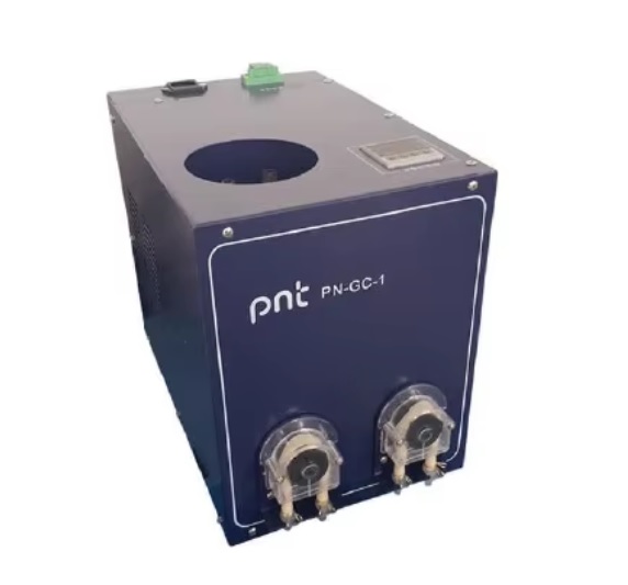
Thiết bị làm lạnh khí CEMS Gas analyzer condenser PN-GC-1 with dual cold chamber and two peristaltic pumps
Thiết bị làm lạnh khí CEMS Gas analyzer condenser PN-GC-1 with dual cold chamber and two peristaltic pumps
Tình trạng sản phẩm:
Compressor condenser
PN-GC-1
- 1. Overview
This device is a compressor type condenser specially designed and produced for various analytical instruments (such as infrared analyzers) used in industrial process control and environmental protection online detection of gas components ( CO, CO2, O2, SO2 , etc. ) . It uses the principle of compressor refrigeration and a specially designed heat exchanger to fully refrigerate the high-temperature and humid sample gas in the heat exchanger, so that the humid and hot gas in it is condensed into liquid. At the same time, the condensed liquid is discharged by a peristaltic pump (or other methods) to achieve gas-liquid separation. The water content in the sample gas to be tested is greatly reduced to ensure the normal operation of the analytical instrument.
- 2. Important safety information
2.1 Safety Tips :
Before installation and initial startup, please be sure to read this instruction manual carefully and pay attention to the safety tips.
The condenser is refrigerated by the compressor. It cannot be inverted during transportation and installation. The compressor has thermal overload protection. After stopping, you must wait for five minutes before restarting to allow the compressor to recover.
This condenser is an electrical device, and some parts of the device carry dangerous voltage during operation. Therefore, when inspecting or maintaining the device, you must disconnect the power supply before opening the cover!
This condenser is suitable for installation in safe non-hazardous areas and is not suitable for flammable or toxic sample gases.
2.2 Function Tips :
This condenser is used to reduce the dew point of the humid sample gas. Only filtered gas is allowed to be used. In addition, please note that the maximum flow rate and dew point of the sample gas at the gas inlet cannot exceed the regulations of this dryer.
- 3. Installation instructions:
3.1 Installation environment :
Ensure good ventilation at the front (back) and left and right ends, avoid heat sources at the top, and leave at least 100mm of space height at the top (the dryer discharges hot air from the top to the outside).
Pay attention to the ambient temperature limit of -5 ℃ ~ +50 ℃.
The condenser should be placed as close to the sampling point as possible.
Condensation water may be corrosive, so please pay attention to the collection of condensation water.
3.2 Installation:
3.2.1 Installation dimensions are shown in the figure below:
3.2.2 Sample gas connection: two in and two out.
3.2.3 Condensate connection
Condensate is usually acidic and appropriate safety measures should be taken at the discharge point and relevant regulations for acid discharge should be followed.
The water and gas pipe connection interfaces must be leak-free, which can be checked as follows:
Connect one end of a U- tube pressure gauge to the sample gas outlet pipe, close the condensate outlet with a valve, connect air (or N2 ) with a pressure of 0.01MPa to the sample gas inlet, and close the valve when there is a 0.01MPa pressure difference on the U -tube pressure gauge . After 5 minutes , observe the change of the water level in the U -tube. The water level drop in the U - tube should not be greater than 2mm/min . A larger pressure drop indicates a leak.
3.2.4 Electrical connection
Please check the power supply voltage, frequency and power consumption ( AC220V , 50Hz , 0.15kw )
Notice:
The condenser housing and the power cord plug are connected to the ground. Please ground the socket well.
- 4. Startup and shutdown
4.1 Initial startup
4.1.1 Check all gas connections for leaks and ensure electrical connections are correct .
4.1.2 Turn on the power , the compressor should start, and the digital display will indicate the temperature. After working for a few minutes, the displayed temperature will turn on. It takes about 15 to 20 minutes to reach a stable cooling temperature ( 3 to 4 °C) .
Note: The digital display monitors the heat exchanger temperature. As long as the sample gas cooling temperature ( 3 to 4 °C) is not reached, the sample gas must be cut off.
At this point the gas condenser can start working and the gas can be introduced at the specified flow rate.
4.2 Shutdown
Turn off the sample gas, let the condenser continue to work for 10 minutes, and then disconnect the power supply.
- 5. Maintenance
This condenser is designed for long term continuous operation with minimum maintenance.
5.1 If the heat exchanger becomes dirty, its performance will be reduced. You can remove the connecting pipes and flush the pipes inside the heat exchanger with clean water. Use a dry brush to brush off the condensed particles attached to the surface of the heat exchanger.
5.2 If the connecting pipes are aged and deteriorated, they should be replaced as required.
- 6. Temperature indicator monitor and fault diagnosis
6.1 Digital Temperature Indicator Monitor
The digital temperature indicating monitor measures and displays the temperature of the heat exchanger using a PT100 sensor.
If the temperature displayed is between 3 and 4 °C, it indicates normal operation. See the appendix for the circuit diagram.
Power monitoring: The temperature indicator monitor displays temperature, indicating that the power is on.
6.2 Fault diagnosis
| Phenomenon | Causes and Corrections |
| Digital display is not lit | Check the power supply: Open the top cover and measure whether the digital display has power supply voltage ( 220V ) If yes, it means the display is broken and you need to replace it. If no, it means there is something wrong with the measuring circuit and you need to check the relevant circuit or request repair service. |
| Temperature above 10 ℃ | The compressor is broken, replace it. If the condenser fan does not rotate, open the upper cover and check whether the fan power connection plug is disconnected. If it is disconnected, please connect it. When the plug is working normally, there is AC220V power supply. If not, there is a problem with the control circuit; if there is, it means that the fan is broken and the fan should be replaced. The sample gas flow rate is too high. Check its flow rate and reduce the sample gas flow. Heat exchanger is dirty. Check, flush. The refrigerant charge in the compressor is leaking. Call for service. |
| Temperature below 0 ℃ | The capacity regulating valve does not work. Check whether the regulating valve has voltage. Its normal working voltage is AC220V . If not, there is a problem with the control circuit; if so, the regulating valve is broken and needs to be replaced. |
| Sample is moist | Same as temperature above 10 °C |
| Sample outflow rate is too small (Air intake is normal) | The sample gas condensation pipeline or the preset filter is blocked by impurities. Flush the pipeline or filter. The sample gas condensation pipeline interface is leaking. Perform a pressure test to find out the leak and take appropriate measures to stop the leak. |
- 7. Technical indicators
7.1 Start - up time: about 15 minutes ;
7.2 Cooling power at +25 ℃ : 100W ;
7.3 Ambient temperature: -5 ℃~ +50 ℃ ;
7.4 Dew point at outlet : +3 ℃ ;
7.5 Dew point stability : 0.5K ;
7.6 Power supply , power consumption: 220V , 50Hz (using 5A fuse) 0.15kw (maximum) ;
7.7 Refrigerant : R134
7.8 Dimensions : 340 × 250 × 280mm (length × width × height);
7.09 Maximum sample gas flow rate: 2 × 100L / h ;
Inlet dew point of sample gas: +70 ℃ ;
Maximum sample gas introduction temperature: +140 ℃ ;
Maximum working gas pressure: 0.15MPa
Pressure loss: 40Pa
Volume: 100ml
Sample gas connection: 4x6/6x8mm
Condensate drain connection: 4x6mm
-
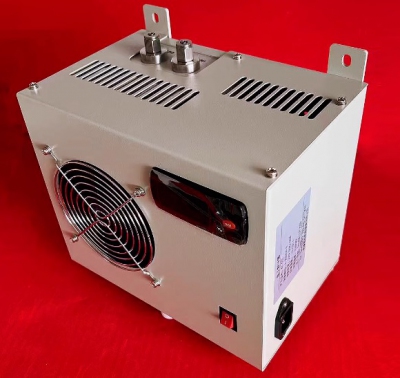
- Thiết bị làm lạnh khí CEMS Gas Analyzer Universal Electronic Refrigerator Condenser Dehumidifier KC-300 Liên hệ
-
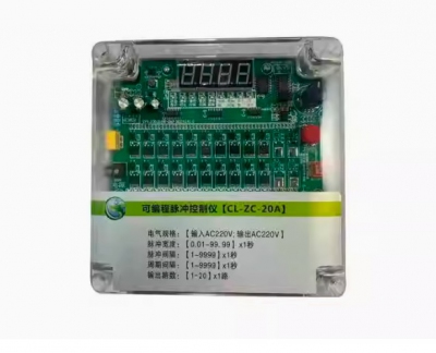
- Bộ điều khiển van cho lọc bụi túi Programmable pulse controller bag filter off-line electromagnetic pulse valve pulse controllerDCM-LC-8D DCM-LC-12D DCM-LC-12A DCM-LC-16D DCM-LC-20D DCM-LC-20A DCM-LC-24D DCM-LC-30D DCM-LC-30A Liên hệ
-
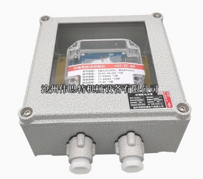
- Bộ điều khiển van cho lọc bụi túi vỏ phòng nổ Explosion-proof pulse controller VST type online and offline bag dust collector control instrument 24V220V Liên hệ
-
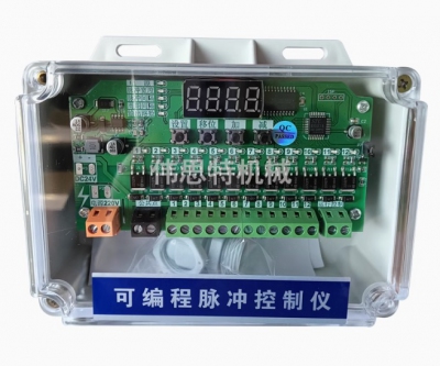
- Bộ điều khiển van cho lọc bụi túi Program-controlled pulse valve cylinder CS-10D/12/16/20/24/28D/36D/70D offline programmable Liên hệ
-
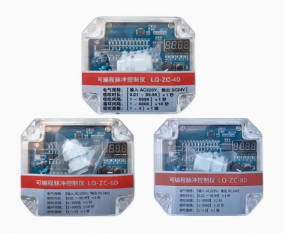
- Bộ điều khiển van cho lọc bụi túi Programmable pulse controller LQ-ZC-8D 10D 12D 20D 30D-way dust removal pulse lift valve offline controller Liên hệ
-
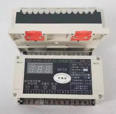
- Bộ điều khiển van cho lọc bụi BFZD pulse program controller PLC-20 card slot control board pulse controller PLC-20 program control Liên hệ
-
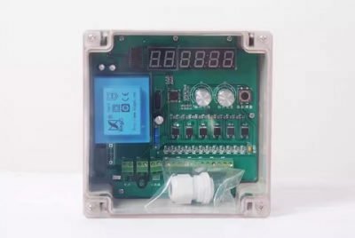
- Bộ điều khiển van cho lọc bụi Pulse controller dust collector offline universal 1 to 40-way MT-8/10/12/20/30-D/A Liên hệ
-
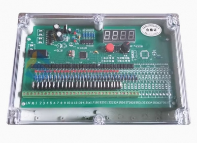
- Bộ điều khiển van cho lọc bụi SXC-8A1/8B2-8/10/16/20/30/40 Pulse Controller Dust Removal Solenoid Pulse Valve Controller Liên hệ
TÂN THÀNH CAM KẾT
- Sản phẩm, hàng hóa chính hãng.
- Giá cả cạnh tranh.
- Dịch vụ chăm sóc khách hàng tận tâm.
Thông Tin Công Ty
Chính sách và quy định
Hỗ trợ khách hàng
THÔNG TIN LIÊN HỆ:
-------------------------------
CÔNG TY TNHH THIẾT BỊ CÔNG NGHIỆP TTH
Trụ sở: số 124 ngõ 79 Yên Hoà-Cầu giấy-HN
Kinh doanh 1 : 0816.861.515
Kinh doanh 2 : 0836.861.515
Email: tthkinhdoanh@gmail.com
Email: tthkinhdoanh01@gmail.com

