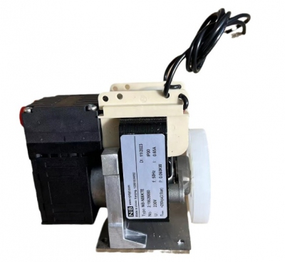
- Bộ lập trình PLC, cáp lập trình
- Màn hình HMI
- Cảm biến, phụ kiện
- Biến tần, khởi động mềm
- Máy cắt, Aptomat, khởi động từ
- Thiết bị đo lường, bảo vệ
- Thiết bị công nghiệp, tự động hóa
- Thủy lực, khí nén, van công nghiệp
- Motor, Servo motor, Servo Amplifier
- Thyristor, Module, SCR, SSR, Diode
- Phụ kiện tủ điện và vỏ tủ điện
- Cáp điện, ống bảo vệ cáp
- Thiết bị điện trung thế, truyền tải
- Thiết bị chống sét, kim thu sét
- Dụng cụ cầm tay, dụng cụ tool
- ATS, UPS, tụ bù, cuộn kháng
-
Thiết bị ngành xi măng, thép, nhiệt điện
-
Thiết bị vật tư điện nhẹ-viễn thông
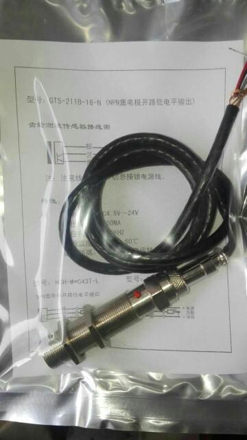
Cảm biến tốc độ, đo tốc độ bánh răng, đo tốc độ trục GTS211B-NPN-16
GTS gear speed sensor:
An advanced speed sensor for non-contact detection of rotating body speed. The measuring range is from 1 rpm to 20,000 rpm. The output square wave signal can be directly
interfaced with TTL, CMOS and other circuits to form a speed measurement/control system.
GTS The product adopts the waterproof structure of round pipe, has the advantages of waterproof, dustproof and oil proof, and can work reliably in harsh environment, especially suitable for industrial control and military projects.
First, the basic technical performance
1, rated detection distance: 2mm
2, detection frequency response: 1Hz ~ 10KHz
3, speed range: 1 ~ 20000rpm (matching with the appropriate gear)
4, working voltage polarity protection and output short circuit protection
5, Working temperature -20~75°C
2. Electrical performance
1. Working voltage: 12~30VDC
2. Static power consumption current: ≤30mA
3. Maximum output current: 50mA
4. Output low level voltage: ≤0.5VDC
5. Rising edge Time: ≤ 2us
6. Falling edge time: ≤ 2us
7. Output mode: NPN open collector output (OC), square wave, duty cycle 50±20%
3. Detection gear
1, modulus: m≥1
2. Gear thickness: ≥4mm
3. Tooth shape: involute or trapezoidal straight tooth
4, gear material: magnetically conductive material (such as 45# steel)
Tình trạng sản phẩm:
IV. Instructions for use
1. Dimensions of the sensor are shown in Figure 1. The sensor is installed with the sensor. The nut is fixed to the mounting hole and the fixing device is recommended
Sensors using non-magnetic materials (copper, stainless steel, etc.) should be mounted on the tooth surface. The spacing between the tooth surface and the front end of the sensor should not be greater than the rated detection distance.
2, the detection gear may be a conventional machine or a special gear of the work gear, but it shall comply with three items, shall make
possible to use a smaller detection distance, the gear should be used as a large high permeability material Modulus.
3. The actual speed range varies according to the number of teeth of the gear N. It can be calculated by the following formula: the
lower limit of the speed range: Vmin= (rpm); the upper limit of the speed range: Vmax= (rpm)
4. See Figure 2 for the wiring diagram. A sensor housing connected to the shield layer and the shield line, the user at the receiving end should be connected to system ground shield
5, to enhance the ability of anti-jamming signal, the sensor can be a current output, and at the receiving end compartment optocoupler from
-
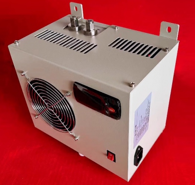
- Thiết bị làm lạnh khí CEMS Gas Analyzer Universal Electronic Refrigerator Condenser Dehumidifier KC-300 Liên hệ
-
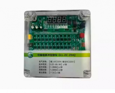
- Bộ điều khiển van cho lọc bụi túi Programmable pulse controller bag filter off-line electromagnetic pulse valve pulse controllerDCM-LC-8D DCM-LC-12D DCM-LC-12A DCM-LC-16D DCM-LC-20D DCM-LC-20A DCM-LC-24D DCM-LC-30D DCM-LC-30A Liên hệ
-
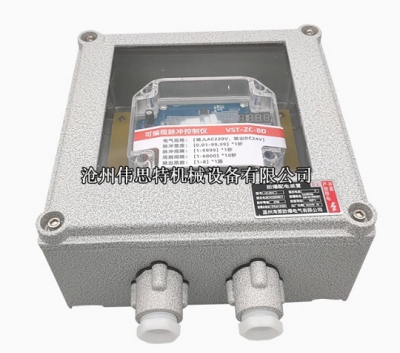
- Bộ điều khiển van cho lọc bụi túi vỏ phòng nổ Explosion-proof pulse controller VST type online and offline bag dust collector control instrument 24V220V Liên hệ
-
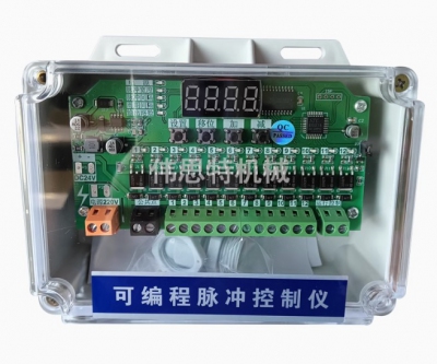
- Bộ điều khiển van cho lọc bụi túi Program-controlled pulse valve cylinder CS-10D/12/16/20/24/28D/36D/70D offline programmable Liên hệ
-
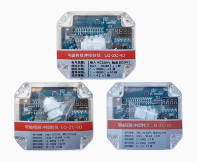
- Bộ điều khiển van cho lọc bụi túi Programmable pulse controller LQ-ZC-8D 10D 12D 20D 30D-way dust removal pulse lift valve offline controller Liên hệ
-
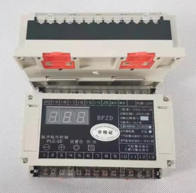
- Bộ điều khiển van cho lọc bụi BFZD pulse program controller PLC-20 card slot control board pulse controller PLC-20 program control Liên hệ
-
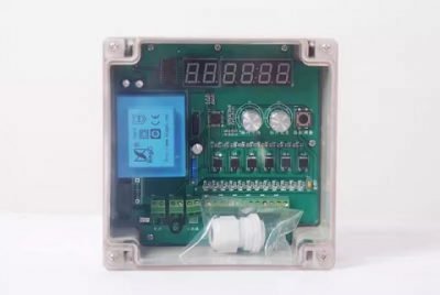
- Bộ điều khiển van cho lọc bụi Pulse controller dust collector offline universal 1 to 40-way MT-8/10/12/20/30-D/A Liên hệ
-
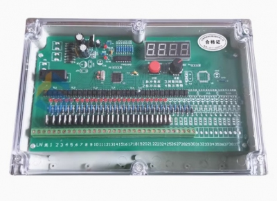
- Bộ điều khiển van cho lọc bụi SXC-8A1/8B2-8/10/16/20/30/40 Pulse Controller Dust Removal Solenoid Pulse Valve Controller Liên hệ
TÂN THÀNH CAM KẾT
- Sản phẩm, hàng hóa chính hãng.
- Giá cả cạnh tranh.
- Dịch vụ chăm sóc khách hàng tận tâm.
Thông Tin Công Ty
Chính sách và quy định
Hỗ trợ khách hàng
THÔNG TIN LIÊN HỆ:
-------------------------------
CÔNG TY TNHH THIẾT BỊ CÔNG NGHIỆP TTH
Trụ sở: số 124 ngõ 79 Yên Hoà-Cầu giấy-HN
Kinh doanh 1 : 0816.861.515
Kinh doanh 2 : 0836.861.515
Email: tthkinhdoanh@gmail.com
Email: tthkinhdoanh01@gmail.com

