- Bộ lập trình PLC, cáp lập trình
- Màn hình HMI
- Cảm biến, phụ kiện
- Biến tần, khởi động mềm
- Máy cắt, Aptomat, khởi động từ
- Thiết bị đo lường, bảo vệ
- Thiết bị công nghiệp, tự động hóa
- Thủy lực, khí nén, van công nghiệp
- Motor, Servo motor, Servo Amplifier
- Thyristor, Module, SCR, SSR, Diode
- Phụ kiện tủ điện và vỏ tủ điện
- Cáp điện, ống bảo vệ cáp
- Thiết bị điện trung thế, truyền tải
- Thiết bị chống sét, kim thu sét
- Dụng cụ cầm tay, dụng cụ tool
- ATS, UPS, tụ bù, cuộn kháng
-
Thiết bị ngành xi măng, thép, nhiệt điện
-
Thiết bị vật tư điện nhẹ-viễn thông
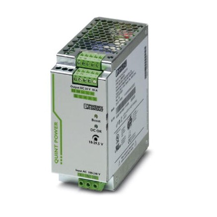
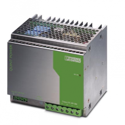
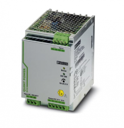
Bộ nguồn Phoenix, Phoenix power supply module three-phase QUINT-PS/ 3AC/24DC/10 24V 10A ,2866705
product description
The QUINT POWER power supplyQUINT POWER circuit breakers provide maximum functionality and can be quickly thermally decoupled at six times the rated current, providing selective system protection and cost savings. Precautionary function monitoring ensures extremely high system availability because it can issue critical operating status reports before a fault occurs.
With the static power reserve POWER BOOST, heavy loads can be reliably started. The adjustable voltage covers all ranges between 5 V DC ... 56 V DC.
size
| width | 60 mm |
|---|---|
| height | 130 mm |
| depth | 125 mm |
| Spare terminal width | 122 mm |
| Spare terminal height | 130 mm |
| Alternate assembly view | 63 mm |
Environmental conditions
| Protection level | IP20 |
|---|---|
| Ambient temperature (running) | -25 °C ... 70 °C (> 60 °C Derating: 2.5 %/K) |
| Ambient temperature (debug type test) | -40 °C |
| Ambient temperature (storage/transportation) | -40 °C ... 85 °C |
| Maximum relative humidity allowed (operating) | ≤ 95 % (no condensation at 25 ° C) |
| Anti-interference | EN 61000-6-2:2005 |
| Installation height | 4500 m |
Tình trạng sản phẩm:
Input data
| Rated input voltage range | 3x 400 V AC ... 500 V AC |
|---|---|
| Input voltage range | 3x 320 V AC ... 575 V AC |
| 2x 360 V AC ... 575 V AC | |
| 450 V DC ... 800 V DC | |
| AC frequency range | 45 Hz ... 65 Hz |
| DC frequency range | 0 Hz |
| PE discharge current | < 3.5 mA |
| Electricity consumption | 3x 1.2 A (400 V AC) |
| 3x 1 A (500 V AC) | |
| 0.4 A (600 V DC) | |
| Rated power consumption | 259 W |
| Shock surge current | < 15 A (typical) |
| Power failure bypass | > 30 ms (400 V AC) |
| > 46 ms (500 V AC) | |
| Choose the right fuse | 6 A ... 16 A (AC: Characteristics B, C, D, K) |
| Protection name | Transient surge protection |
| Protection circuit/component | Varistor, gas discharge tube |
Output Data
| Rated output voltage | 24 V DC ±1 % |
|---|---|
| Setting range of output voltage (U Set ) | 18 V DC ... 29.5 V DC (> 24 V DC, stable capacity limit) |
| Rated output current (I N ) | 10 A (-25 °C ... 60 °C, U OUT = 24 V DC) |
| POWER BOOST (I Boost ) | 15 A (-25 ° C ... 40 ° C constant, U OUT = 24 V DC ) |
| Selective fuse (I SFB ) | 60 A (12 ms) |
| attenuation | 60 °C ... 70 °C (2.5%/K) |
| Even | Yes, for redundancy and increased capacity |
| Concatenation | Yes |
| Control deviation | < 1 % (load change, static 10% ... 90%) |
| < 3% (load change, dynamic 10% ... 90%) | |
| < 0.1 % (the input voltage varies by ±10%) | |
| Residual wave | < 20 mV SS (rated value) |
| Output Power | 240 W |
| Typical response time | < 0.45 s |
| Peak switching voltage rated load | < 20 mV SS (20MHz at rated value) |
| Maximum idle power consumption | 7 W |
| Maximum rated load power loss | 19 W |
Overview
| net weight | 1.1 kg |
|---|---|
| Working voltage display | Green LED |
| effectiveness | > 93 % (at 400V AC and rated) |
| Insulation voltage input / output | 4 kV AC (type test) |
| 2 kV AC (conventional test) | |
| Insulation voltage input / PE | 3.5 kV AC (type test) |
| 2 kV AC (conventional test) | |
| Insulation voltage output / PE | 500 V DC (conventional test) |
| Protection level | I |
| MTBF (IEC 61709, SN 29500) | > 1100000 h (25 °C) |
| > 630000 h (40 °C) | |
| > 280000 s (60°C) | |
| Installation location | Horizontal DIN rail NS35, EN60715 |
| Assembly instructions | Can be installed side by side; horizontal spacing 5 mm, 15 mm for active components, 50 mm vertical spacing |
-
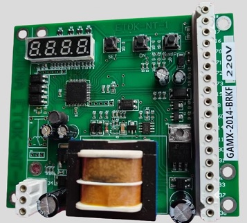
- Mạch điều khiển cho van actuator GAMX-2014-BRKF Electric Actuator Control Board GAMX-2014-BRKF 380V GAMX-2014-BRKF 220V Liên hệ
-
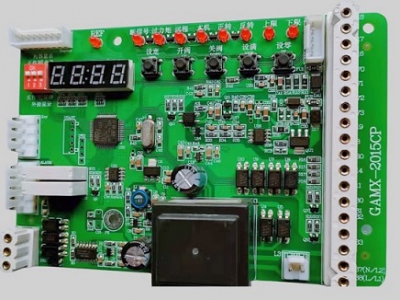
- Mạch điều khiển cho van actuator GAMX-2015CP Electric Actuator Control Board GAMX-2015CP 220V GAMX-2015CP 380V Liên hệ
-
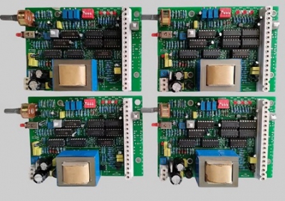
- Mạch điều khiển cho van actuator GAMX-TD518S Electric actuator control board GAMX-S518S GAMX-L1840 Liên hệ
-
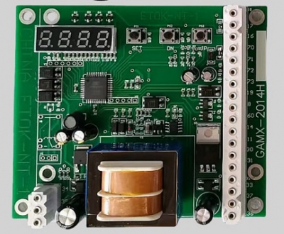
- Mạch điều khiển cho van actuator GAMX-2014H Electric Actuator Control Board GAMX-2014H 220V GAMX-2014H 380V Liên hệ
-
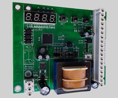
- Mạch điều khiển cho van actuator GAMX-2013H Electric Actuator Control Board GAMX-2013H 220V GAMX-2013H 380V Liên hệ
-
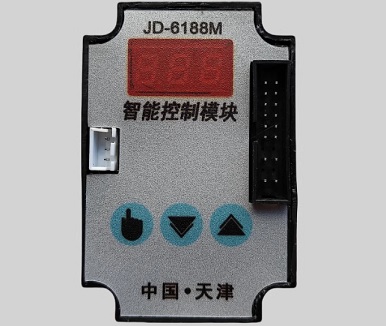
- Mạch điều khiển cho van actuator JD-6188M Intelligent Control Module Electric Actuator Controller Liên hệ
-
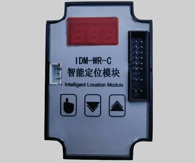
- Mạch điều khiển cho van actuator IDM-WR-C Intelligent Positioning Module Electric Actuator Controller Liên hệ
-
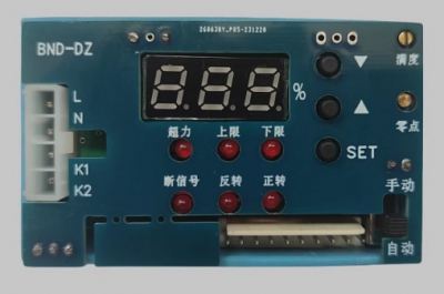
- Mạch điều khiển cho van actuator BND-DZ Intelligent Electric Actuator Intelligent Control Module Liên hệ
TÂN THÀNH CAM KẾT
- Sản phẩm, hàng hóa chính hãng.
- Giá cả cạnh tranh.
- Dịch vụ chăm sóc khách hàng tận tâm.
Thông Tin Công Ty
Chính sách và quy định
Hỗ trợ khách hàng
THÔNG TIN LIÊN HỆ:
-------------------------------
CÔNG TY TNHH THIẾT BỊ CÔNG NGHIỆP TTH
Trụ sở: số 124 ngõ 79 Yên Hoà-Cầu giấy-HN
Kinh doanh 1 : 0816.861.515
Kinh doanh 2 : 0836.861.515
Email: tthkinhdoanh@gmail.com
Email: tthkinhdoanh01@gmail.com

