- Bộ lập trình PLC, cáp lập trình
- Màn hình HMI
- Cảm biến, phụ kiện
- Biến tần, khởi động mềm
- Máy cắt, Aptomat, khởi động từ
- Thiết bị đo lường, bảo vệ
- Thiết bị công nghiệp, tự động hóa
- Thủy lực, khí nén, van công nghiệp
- Motor, Servo motor, Servo Amplifier
- Thyristor, Module, SCR, SSR, Diode
- Phụ kiện tủ điện và vỏ tủ điện
- Cáp điện, ống bảo vệ cáp
- Thiết bị điện trung thế, truyền tải
- Thiết bị chống sét, kim thu sét
- Dụng cụ cầm tay, dụng cụ tool
- ATS, UPS, tụ bù, cuộn kháng
-
Thiết bị ngành xi măng, thép, nhiệt điện
-
Thiết bị vật tư điện nhẹ-viễn thông
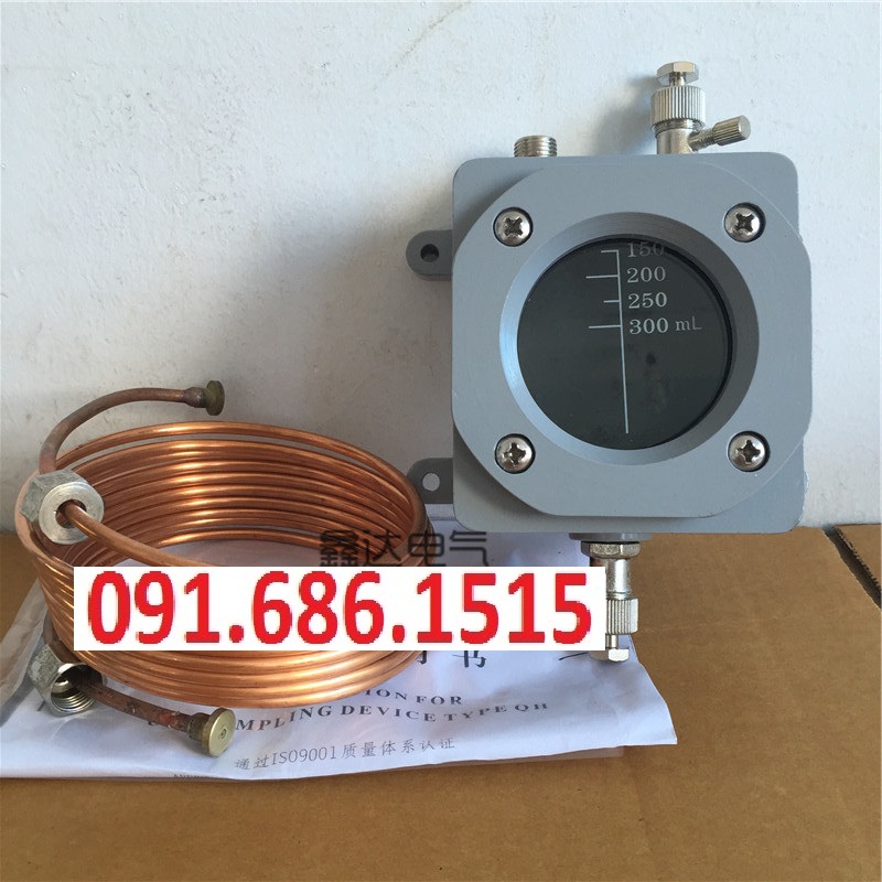
QH1-500 gas relay waterproof gas box 3.5 m copper plate copper tube QJ4 series gas relay
First, the product uses:
This product is mainly used for gas relay connection, oil discharge and gas extraction installed in the upper part of the transformer.
Second, the structure and working principle:
The gas take-up box is in the form of a Unicom structure. The connecting pipe is connected to the gas relay side wall joint through the upper end nut, and the lower end is connected to the gas taking box. The gas box is installed on the transformer tank wall, and the gas inside the gas relay is collected through the connecting pipe. Inside the gas box to get gas on the ground at any time.
The gas relay (hereinafter referred to as the relay) is an oil-immersed transformer with an oil storage cabinet and a protection device for the on-load tap changer.The relay is installed in the connecting pipeline between the transformer and the oil tank of the on-load tap changer and the oil conservator.
Technical parameters:
oil flow speed range and factory setting value of the trip contact action
QJ4 series gas (gas) relay model:
QJ4-80-TH QJ4-25-TH QJ4-50-TH QJ1-50 QJ1-25 QJ4-80
Flow rate range 1.0m/s
factory setting 1.0m/s
1. Relay pipe diameter:
QJ4-25 type is ф25, QJ1-5O is ф50, QJ1-80 is ф80
2. Relay working temperature: -30° C- +95 °C
3. Signal contact action gas capacity: 250-300cm3
4. Contact rated capacity: 220V 0.3A, 110V 0.6A (S 5X10 S)
5. Insulation strength: 2000V/nim
6. Sealing performance: The relay is filled with transformer oil, Pressurized at room temperature for 200Kpa/20min without leakage.
7. Seismic resistance: When the vibration frequency (positive Hong wave) is 4-20 Hz and the acceleration is 4g, the relay does not malfunction. (g is gravitational acceleration)
leads can lead the bleed valve with light gas to the main transformer (with a lead box)
III: Product introductionGas relay is a main protection device for oil-immersed transformers and oil-immersed on-load tap-changers. The gas relay is installed on the connecting line between the transformer and the oil conservator. When the internal fault of the transformer causes the oil to decompose to generate gas or cause the oil flow to be impulsive, the contact of the gas relay acts to turn on the designated control loop and signal or Automatically cut off the transformer.Four: product propertiesambient temperature -40 ~ 45 °C. Allowable operating temperature: -40 to +105 °C.Installation method: The axis of the relay pipeline should be parallel to the transformer cover, allowing the end to the oil conservator to be slightly higher, but the inclination of the axis to the horizontal plane should not exceed 4%. Gas relays are a major protection device for oil-immersed transformers and oil-immersed on-load tap-changers. The relay core structure, the upper part of the relay core consists of an open cup float, a weight, a magnet and a reed contact to form a gas volume device that acts on the signal, and the lower part is composed of a baffle, a spring, an adjustment rod, a magnet and a reed contact. The flow rate device for tripping. The gas plug on the cover is used for exhausting during installation and for extracting faulty gas during operation. The probe is used to check the flexibility and reliability of the trip mechanism.Five: How to use1. Before the new factory relay is installed, the relay core must be taken out and the strap for transport fixing must be removed. Also check whether all the fasteners are loose, whether the open cup float and the baffle are flexible, and whether the contacts are reliably opened and closed. 2. The relay should be installed on the connecting line between the oil-immersed transformer and the oil conservator, and the inner diameter of the connecting pipe should be The diameter of the pipe with the relay is the same, and the arrow on the relay must point to the oil conservator. Allow the oil storage tank end to be slightly higher, but the inclination of the axis of the joint pipe and the horizontal plane shall not exceed 4%, or the method of installing the air guide tube may be adopted to make the internal gas of the transformer easy to be collected in the relay. 3. The installation position of the relay should be convenient. Take the gas sample and observe the relay, and facilitate the inspection of the gas relay on the operation site. The installation position should ensure that the relay core can be smoothly removed from the casing. 4. Adjust the gas volume: change the weight position on the open cup and Change the position of the reed contact to adjust the amount of gas in the signal contact action. After adjustment, tighten the fasteners that are locked and removed. 5. Oil speed adjustment: Adjust the spring-connected adjustment rod to change the tension of the baffle spring. The flow rate value of the trip contact action is set at the factory. The value is shown in the inspection report. After adjustment, the fastener should be locked. The setting of the action flow rate should be performed by the professional on the special flow rate verification device. 6. Adjust the rotation angle of the baffle: adjust the stop screw to change the rotation angle of the baffle, and adjust the distance between the magnet and the reed contact 0.5-1.0mm. In order to ensure reliable opening and closing of the reed contacts.6: Preventive measuresRelays should be visually inspected annually for reliability and signal loop reliability and trip circuit reliability. Relays that have been operated should be opened once every two years for internal structural and operational reliability checks. The relay that has been operated should be tested for power frequency withstand voltage every five years.Seven: Function and characteristicsGas relays are a major protection device for oil-immersed transformers and oil-immersed on-load tap-changers. The relay core structure, the upper part of the relay core consists of an open cup float, a weight, a magnet and a reed contact to form a gas volume device that acts on the signal, and the lower part is composed of a baffle, a spring, an adjustment rod, a magnet and a reed contact. The flow rate device for tripping. The gas plug on the cover is used for exhausting during installation and for extracting faulty gas during operation. The probe is used to check the flexibility and reliability of the trip mechanism. When the relay is in normal operation, its internal part is filled with transformer oil, and the open cup float is tilted up. When there is a slight fault inside the transformer, the gas generated by the decomposition of the transformer oil accumulates in the air chamber at the upper part of the relay, forcing the oil level to drop, and the open cup float descends to a certain position, and the magnet on the spring makes the dry spring contact Pull in, turn on the signal loop, and send out an alarm signal.If the transformer leaks due to the oil tank, the oil level drops as well as the signal circuit, and an alarm signal is issued. When a serious fault occurs inside the transformer, the pressure in the fuel tank rises instantaneously, and oil surge will occur, causing the oil flow to flow toward the oil conservator when the baffle is driven. When the baffle is rotated to a certain position, the upper baffle The magnet pulls the dry spring contact and turns on the trip circuit. The power supply of the transformer is directly cut off without prior warning, thereby protecting the transformer.
Tình trạng sản phẩm:
Eight: Cautions Relays are important safety protection devices for oil-immersed transformers. Therefore, the power sector has special regulations. For example, it must be commissioned, adjusted, and issued by the inspection department before it can be put into use. Therefore, the commissioning and flow rate setting work should be in accordance with relevant regulations. carried out.
-
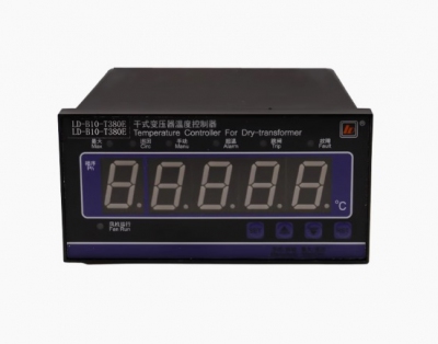
- Đồng hồ đo nhiệt độ LD-B10T380DEF dry-type transformer thermostat temperature controller power supply 380V Liên hệ
-
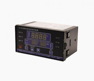
- Đồng hồ đo nhiệt độ LD-B32-12D-1112 LD-B32-12E-1112 LD-B32-12F-1112 LD-B32-12EF-1112 Fujian Lide LD-B32-12D-1112 dry-type transformer thermostat temperature and humidity controller Liên hệ
-
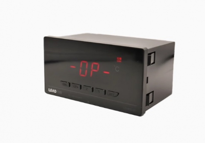
- Đồng hồ đo nhiệt độ Temperature and Humidity Controller LD-B30-30D LD-B30-30E LD-B30-30F LD-B30-30EF LD-B30-30RD LD-B30-30RE LD-B30-30REF LD-B30-30HD LD-B30-30HE LD-B30-30HRD LD-B30-30HRE LD-B30-20D LD-B30-20E LD-B30-20EF Liên hệ
-
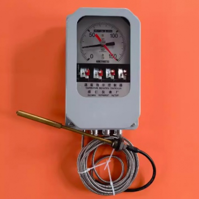
- Đồng hồ đo nhiệt độ dầu máy biến áp lực, Huanren Instrument Factory BWY-804B (TH) Temperature Indicating Controller Oil Level Thermometer Liên hệ
-
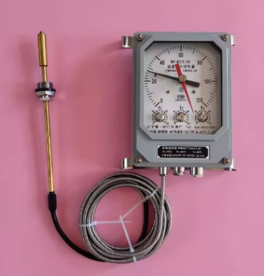
- Đồng hồ đo nhiệt độ dầu máy biến áp lực, Huanren Instrument Factory BWY-803B (TH) Transformer Oil Level Thermometer Oil Temperature Meter Thermostat Liên hệ
-
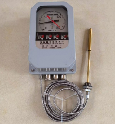
- Đồng hồ đo nhiệt độ cuộn dây máy biến áp lực, Huanren Instrument Factory BWR-04C (TH) Transformer Winding Thermometer Winding Liên hệ
-
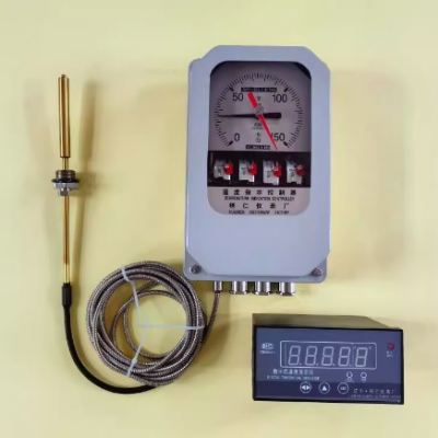
- Đồng hồ đo nhiệt độ dầu máy biến áp lực, Huanren Instrument Factory BWY-804AJ (TH) / XMZ-22 Transformer Oil Level Thermometer Liên hệ
-
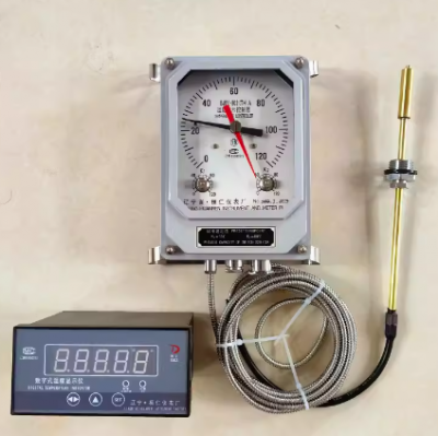
- Đồng hồ đo nhiệt độ dầu máy biến áp lực, Huanren Instrument Factory BWY-802A (TH) / XMZ-22 Oil Level Thermometer Oil Temperature Meter Liên hệ
-
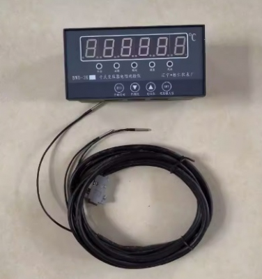
- Bộ điều krhiển nhiệt độ Huanren Instrument Factory BWD-3K Port Dry-type Transformer Resistance Inspection Instrument Liên hệ
-
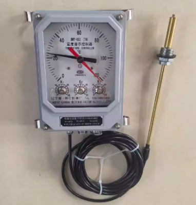
- Đồng hồ đo nhiệt độ máy biến áp lực, Huanren Instrument Factory directly sells BWY-803 (TH) temperature indicating controller Liên hệ
-
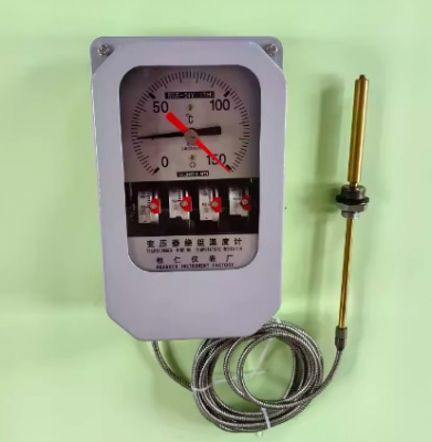
- Đồng hồ đo nhiệt độ cuộn dây máy biến áp lực, Huanren Instrument Factory BWR-04Y (TH) Transformer Winding Thermometer Liên hệ
TÂN THÀNH CAM KẾT
- Sản phẩm, hàng hóa chính hãng.
- Giá cả cạnh tranh.
- Dịch vụ chăm sóc khách hàng tận tâm.
Thông Tin Công Ty
Chính sách và quy định
Hỗ trợ khách hàng
THÔNG TIN LIÊN HỆ:
-------------------------------
CÔNG TY TNHH THIẾT BỊ CÔNG NGHIỆP TTH
Trụ sở: số 124 ngõ 79 Yên Hoà-Cầu giấy-HN
Kinh doanh 1 : 0816.861.515
Kinh doanh 2 : 0836.861.515
Email: tthkinhdoanh@gmail.com
Email: tthkinhdoanh01@gmail.com

